Casio MT-68
This is what i bought:
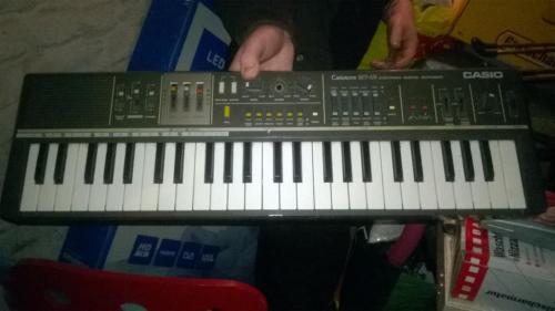
What you see here is a Casio Keyboard from 1983 - it has an internal speaker in the top left corner,
which had to go to make room for the knobs. Speaking of knobs - If you look closly you'll notice that
3 sliderknobs and one rotary knob were missing...I replaced them with selfmade "copies" made of gorillaplastic
(thats something like sugru). The new knobs don't look perfect, but work well. Otherwise it was
working well when i bought it.
Please note: MT-68 is identical to MT-65 (in all but the color which is white for the MT-65) MT-100 uses
nearly the same wireing and the same chips, but ommits a few functions of the MT-65/MT-68 and has a graphic
equalizer, which the MT-68 / MT-65 do not have.
Other Casio Keyboards use the same chips, but may differ stronger in the way they are build: MT-45 , CT-410V, MT-400V
- check shematics (See links in top left corner) for more info on that.
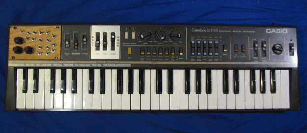
This is what it looks like "finished" (for the time beeing):
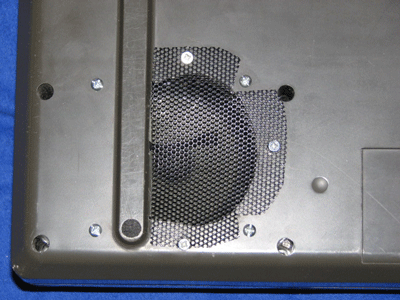
The Speaker, now on the bottom side:
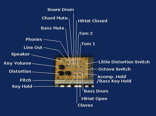
Functions of the switches and Potentiometers:
Internals
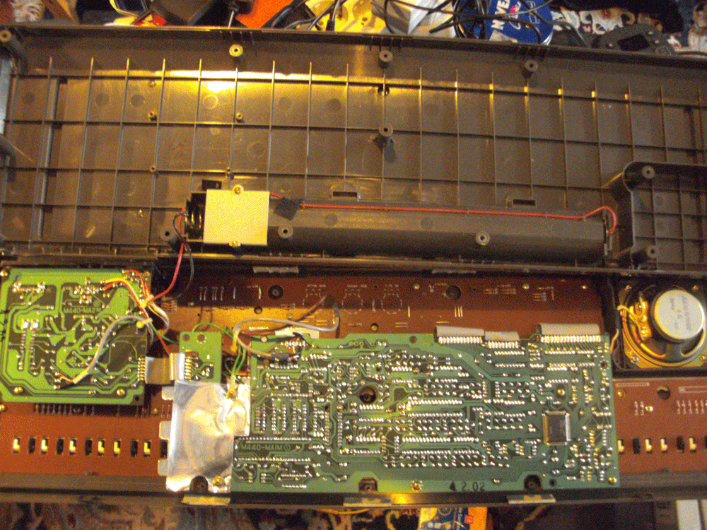
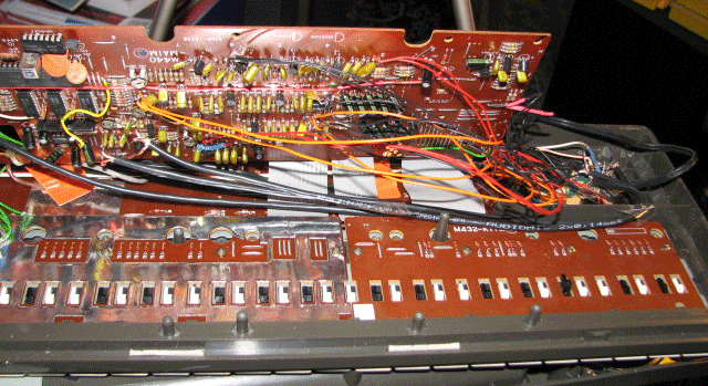
Here you see the internals of the MT-68 unaltered. Central is the M440-MAIM PCB. On the right side u can see its main
chip, a NEC D930G, the actual sound synthesis takes place in the D931 which is directly beneth the letters saying
"M440-MAIM". On the left side you see the amplifer/external conector board named M440-MA2.
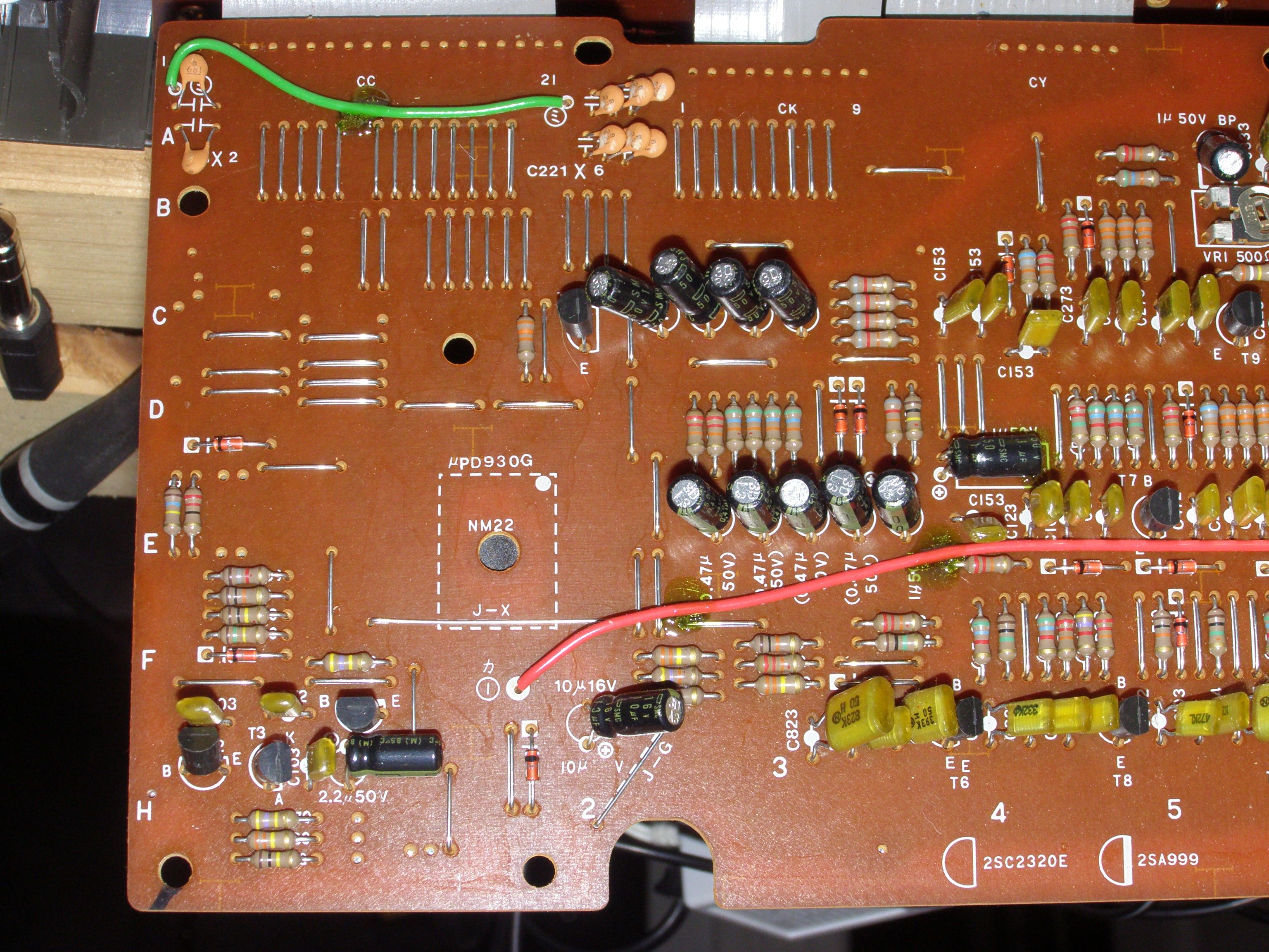
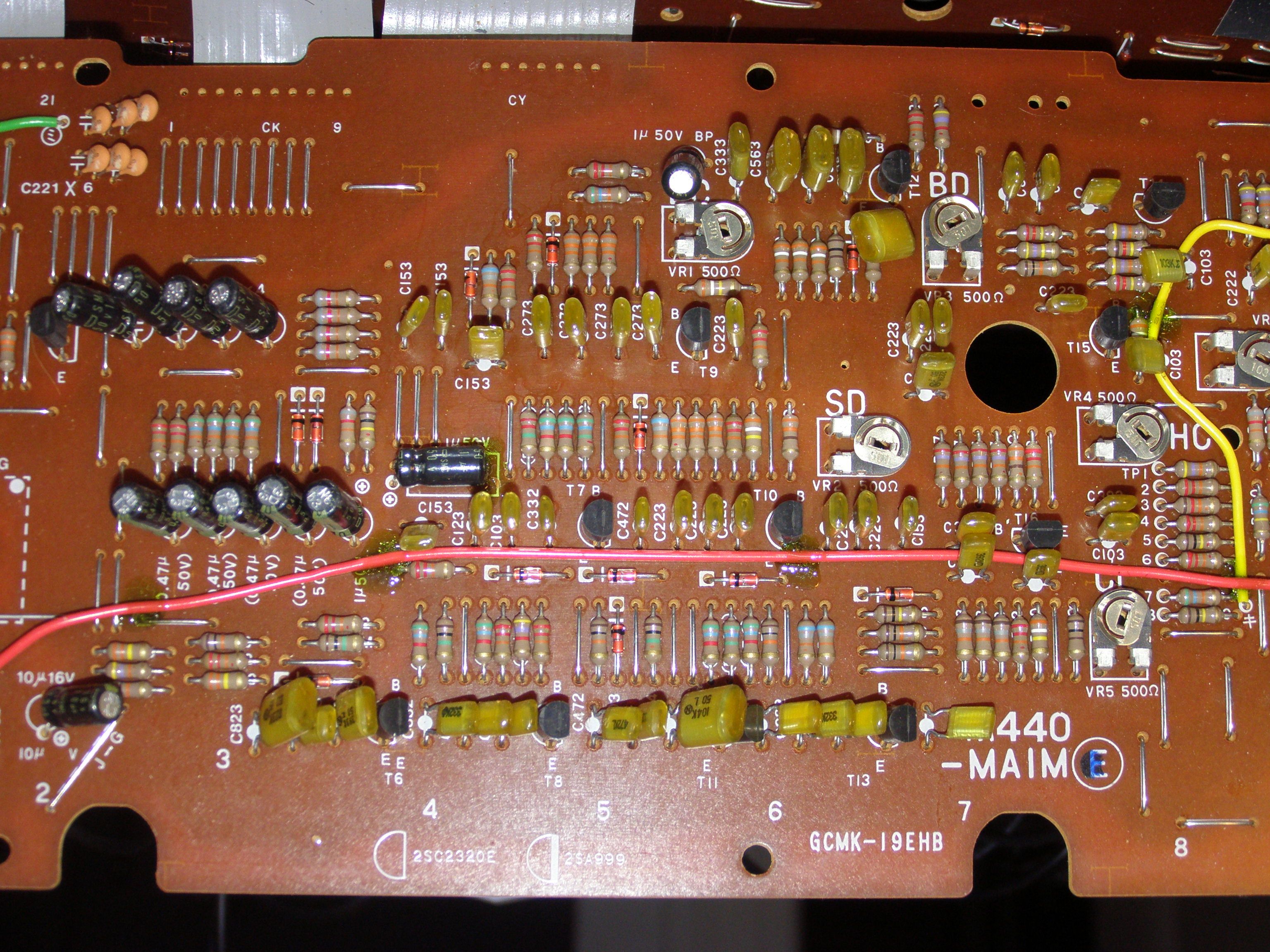
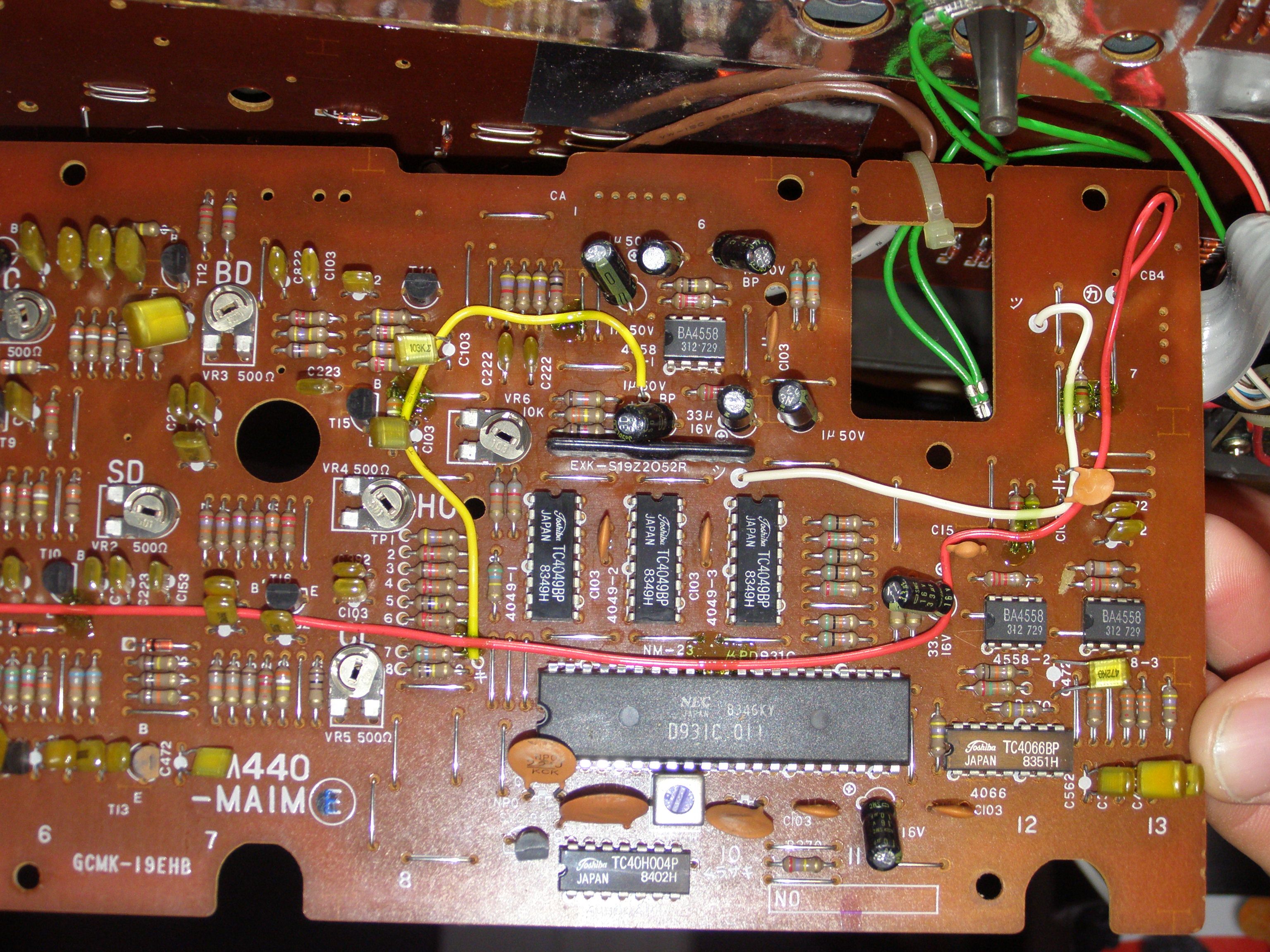
Here you see the component side. Because of the ribbon cable it can not be accessed with the same ease as the other side. For conveniance,
casio even named the analog rythm section instruments, BD for bassdrum, CL for claves and so on.
step by step and spoiler alert
To help others, especially people like me which are more or less new to circuit bending, I show what I did in a step-by-step tutorial
- just pick the steps u like and copy.
Use all info at your own risk! That is: stay away from higher then battery level voltages and
curent, and ask someone who knows a little about soldering and electrictiy to assist you if you are a complete newbee. Be aware that
also the bended "toys" can suffer, up to breaking completly. Also im not liable for any
errors that this page may contain.
Using shielded cables when possible may help to sustain the sound quality.
I use microphone cable from the electronics store: its a twisted pair with shielding, and its relativly thin at around 3.5 - 4 mm or so; also, it was fairly cheap.
Also, a "loop" should not be formed: If a wire goes from the PCB to a switch or potentiometer and another one back to the PCB, as
this will act as an antenna. Better use twisted pairs of wire.
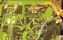
On all photos, if there is a line with a letter or number at one end, i ask you to solder onto the OTHER end of the line, the lines are just there for better visibility.
Speaker Move
In this step the internal speaker is moved to the bottom side of the MT-68, to make space for lots of knobs and switches on the top of the MT-68. Of course,
if the MT-68 stands on a table, it will be far quieter then before. I don't mind, as I use it with headphones or via external speakers most of the time.
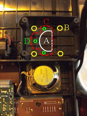
- remove the screws and unsolder the cabel on the speaker terminals
- use the speaker as a gauge to mark holes (B)
- drill holes using a plasic or wood drill into the 4 (B) and one into (A)
- use a jigsaw to cutout (A)
- file down the edges of (A)
- find some old speaker grill (some metal mesh, could even be a kitchen sieve)
and cut it to match (C)
- decide if the mesh/grill goes in the inside of the case, or on the outside
- screw in 3 screws at (D). Use plastic or self-cutting woodscrews, and screw from out- to inside, so one can not cut oneself on the tips of the screws.
- screw the speaker into the new position
- find a kabel that is long enough to connect the speaker (give it some extra length, as the whole MT-68 is better handable,
if this is not so short) and connect to the old cable and the speaker
- use heat shrink tubing to make shure that no unwanted contact is made between cable and PCB.
- close case and test function
Mute for the instruments in the rythm section
Mute for Bass Drum and Claves
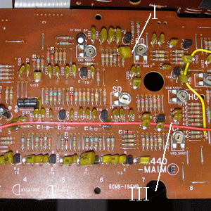
Bass Drum Mute
- desolder one Leg at (I) (at the little red dot)
- solder one wire to the PCB long enough to reach where u want to put the switch
- solder one wire to the open leg of the capacitor (may use heat shrink tubing to prevent short circuit)
- connect switch
- and test
Claves Mute
- desolder one Leg at (III)
- solder one wire to the PCB long enough to reach where u want to put the switch
- solder one wire to the open leg of the capacitor (may use heat shrink tubing to prevent short circuit)
- connect switch
- and test
Mute for Snare Drum
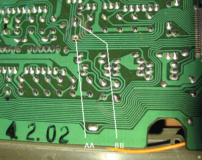
- desolder legs of resistor and capacitor at AA and BB
- connect the open legs of resistor and capacitor to each other, and connect this point to a switch
- connect BB to other side of the switch
- and test
Mute for HiHatOpen
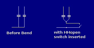
- desolder one leg each of the TWO capacitors at Y
- connect the two open ends with each other
- connect the solder pad at Y with the switch
- connect the two capacitors with the switch
Mute for HiHatClosed
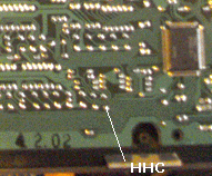
- desolder on leg of capacitor at HHC
- connect wire pair to HHC and open leg of capacitor
- connect to a switch
Mute for Tom1
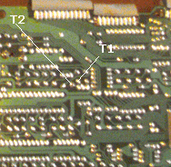
- desolder on leg of capacitor at T1
- connect wire pair to T1 and open leg of capacitor
- connect to a switch
Mute for Tom2
- desolder on leg of capacitor at T2
- connect wire pair to T2 and open leg of capacitor
- connect to a switch
Mute for the Casio-Chord and Bass Accompaniment
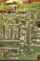
Chord Mute
- important: use a shielded twin cable, idealy twisted
- connect the shielding to ground
- desolder resistor Leg at (C)
- solder one wire to the PCB long enough to reach where u want to put the switch
- solder one wire to the open leg of the resistor
- connect switch
- and test
Bass Mute
- important: use a shielded twin cable, idealy twisted
- connect the shielding to ground
- desolder Leg at (B)
- solder one wire to the PCB long enough to reach where u want to put the switch
- solder one wire to the open leg
- connect switch
- and test
Accompaniment Hold
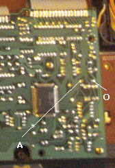
This switches a Note-Hold, or if Accompaniment is on, a Accompaniment-Hold in the Left Section (Bass-Section) of the keyboard.
- desolder one leg of the diode between A and O
- insert switch in series to the diode
- use heat-shrink-tubing to prevent shortcuts
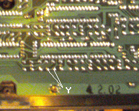
Key Hold
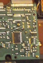
Played notes are sustained. Works with up to 4 notes, the 5th note replaces the 1st, the 6th replaces the 2nd and so on,
so that never more than 4 notes play at any one time (as the melody-section of MT65/68 is 4 voice polyphonic):
- solder one wire to the solderpad at (Y)
- solder one wire to the solderpad at (Z)
- also add the diode (see the passage "Diode")
- connect a switch
- and test
Octave switch
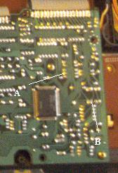
The Octave switch moves the whole melody-key-section one Octave up (or down if it was switched to "up"), only works while MT-68 is in "chord" mode.
- solder one wire to the solderpad at (A)
- solder one wire to the solderpad at (B)
- also add the diode (see the passage "Diode")
- connect a switch
- and test
Diode
Required by Octave and Key-Hold switches
- use any simple cheap standard diode
Speaker Switch
- Just cut one Wire to the Speaker and insert a switch
Phones Switch
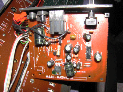
- desolder one leg of resistor at P and connect 2 wires to a switch ( second wire in this photo is on other side of PCB) for Phones switch
Line Out Switch
- desolder one leg of resistor at L and connect 2 wires to a switch ( second wire in this photo is on other side of PCB) for Line Out switch
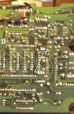
Distortion Potentiometer
- if possible, use a shielded twin cable, idealy twisted
- connect the shielding to ground
- connect one wire to (D)
- connect one wire to (G)
- connect one end of the cable to the center pin of a 100K Ohm Potentiometer
- connect the other end of the cable to one of the outward pins of the 100K Potentiometer
- as this works only in a small portion of the potentiometer, it might be better to put a resistor,
value somewhere between 20K Ohm and 80 Kohm and a 10 or 20 K Potentiometer in series, if you try this
and get a good result, please tell me! you can contact me here.
- test
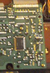
Little Distortion Switch
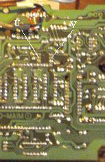
For me, this adds a little extra distortion to the Potentiometer, however, this seems very little and somehow seems to be part of the same circuit as the "Distortion Potentiometer"- Mod - im looking for better connectionpoints for this switch
- if possible, use a shielded twin cable, idealy twisted
- connect the shielding to ground
- connect one wire to (U)
- connect one wire to (V)
- connect switch
- test
Key Volume Potentiometer
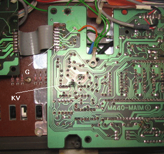
With "Key Volume" i mean a potentiometer that allows to regulate the volume of the played note without changing the volume of the Casio Chord / Bass etc. This needs a shielded cable. connecting the shielding to ground close to the connection on the PCB is recomended.
- desolder one leg of the resistor at KV
- conect the shielding of the cable to ground, I extend the shielding and connected to point G
- connect the two inner wires of the shielded cable to KV and the open resistor leg (on other side of PCB)
- on the other end of the cable connect the two inner wires to the middle and one outer leg of a 470 K Ohms Potentiometer
- also recomended to connect shielding on the potentiometer side to ground, too
- test
Pitch
As I wanted to keep the "tone" regulator (originally a 100K Potentiometer) on the back of the MT-68, didn't find a better conction
then directly to the tone Potentiometer, and it did not work well with a 100K Potentiometer in parallel, this is somehow a little more complex:
- use a desolder pump if possible
- desolder the 100 K Potentiometer, remove all solder as far as possible from the pads (A,B,C and S)
- get two 220 K Potentiometers
- solder 1 Potentiometer into the same place as the old "Tone" Potentiometer was.
- shorten the Potentiometer with sharp cutting plieres (I left about 1 cm for better control)
- file down the edges of the axle
- prepare 3 wires of the same length, mark both ends of one wire (remove a little insulation)
- connect marked wire to B
- connect the other 2 wires to A and C
- braid all 3 wires to one
- solder the marked wire to the central pin of your 2nd 220K Potentiometer
- connect the other 2 wires to the 2 outer pins of the Potentiometer
- test
Last Words about the MT-68
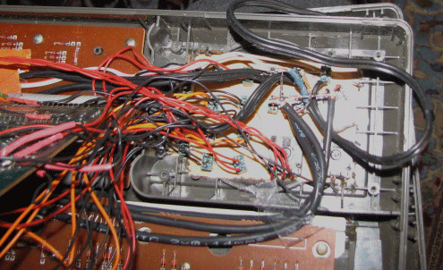
These final two pics are of the connected wires inside, at least most of them, and of the switch and potentiometers rear view.
I think these pics are more a reference in "How not to do it", but may give an impression of the resulting chaos, if you, like me,
just add one bend after the other without any real plan on sorting and organizing the stuff. I had to break away some plastic-wall
around the speaker inside the keyboard, to make room for the wires going in and out of this box when the top of the keyboard is
fitted to the bottom.
thats alll for now... ...more to come... page last updated June 27th 2018
Thank you's go out to Michael for the 1st constructive feedback!
Thank you to Dennis also, who pointed me to a bad mistake: The Snare Drum Mute did not work, but it should work now!
Feedback, positive or negative, about the page or its content, via the
contact form.
also, i'd be very happy to read of any improvments, error corrections or additions on the MT-68 bends.
so ask yourself:
Does it bend? ;)